A voice assistant you build yourself. It listens on the device, thinks in the cloud, answers out loud, and shows what it heard on a little screen.
listening
6
Components
11
Signal pins
4
Build stages
3.3 V
Logic level
01 / What it does
One loop, two halves
A.I.L.Y.N spends its life idle, listening for a wake word entirely on the ESP32-S3 — no internet, no streaming. When it hears the word, it records your question, sends the audio to the cloud to be understood and answered, then speaks the reply back through the speaker while the display shows the text.
Idle
WakeNet listens on-device for the wake word
Record
Capture your question from the mic (16 kHz)
Understand
Speech → text in the cloud
Think
An LLM writes the reply
Speak
Text → speech, played on the speaker
Where the work happens
The wake word is the only AI that runs on the chip — an ESP32-S3 can't run a full assistant locally. Everything after it (speech recognition, the language model, the voice) lives in the cloud and reaches it over Wi-Fi, so you'll need a network and an API key when you get to Stage 4.
02 / Parts list
The kit
Everything below is the exact set of boards this guide is wired for. All logic runs at 3.3 V.
place images/ESP32-S3_Board.png
MCU
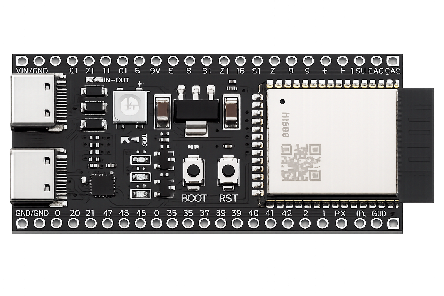
ESP32-S3 dev board
The brain. Dual-core, Wi-Fi, two I2S buses, and the vector instructions WakeNet needs. PSRAM strongly recommended.
place images/ics-43434.jpg
Ears · I2S in
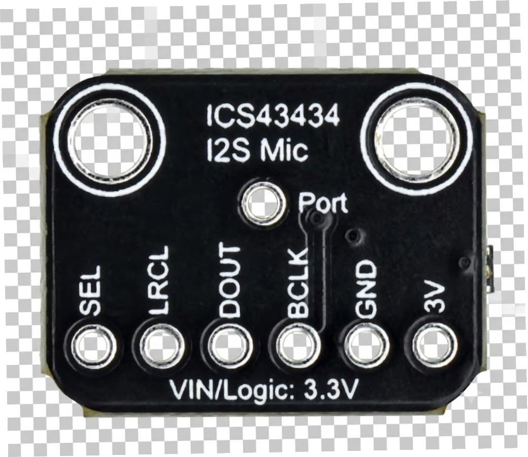
ICS-43434 mic
Digital MEMS microphone. Everything — diaphragm, amp, ADC — is inside the metal can. Don't cover its port hole. 3.3 V only on bare clones.
place images/MAX98357A_Amplifier.png
Voice · I2S out
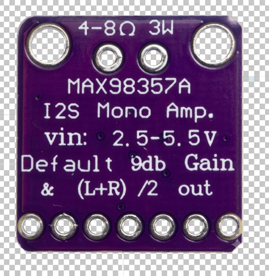
MAX98357A amp
I2S mono class-D amplifier. 2.5–5.5 V in, 3 W out, 9 dB default gain, (L+R)/2 mix. Drives the speaker directly.
place images/40mm_Speaker.png
Sound
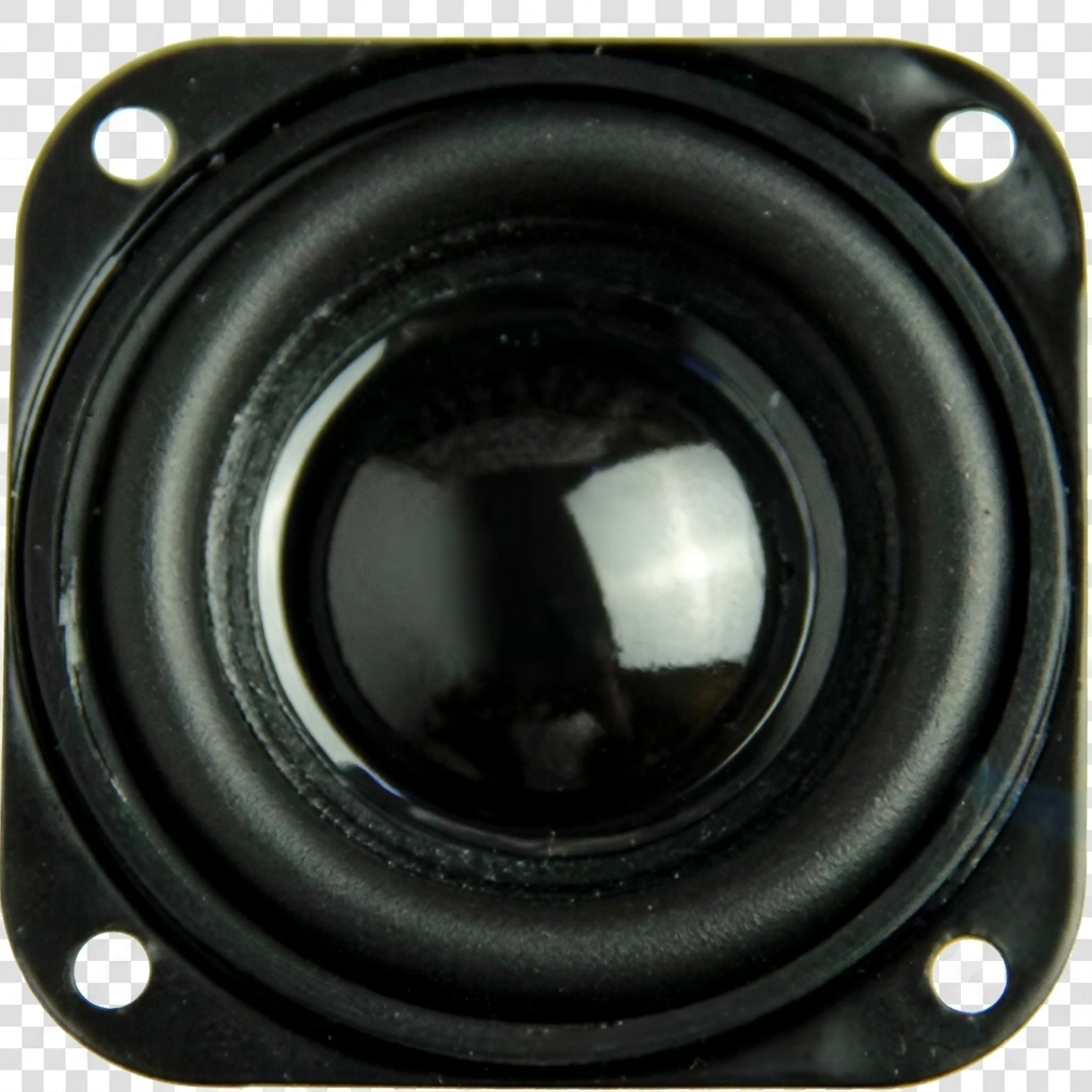
40 mm speaker
4–8 Ω driver. Wires to the amp's + and − terminals — never to the ESP32 directly.
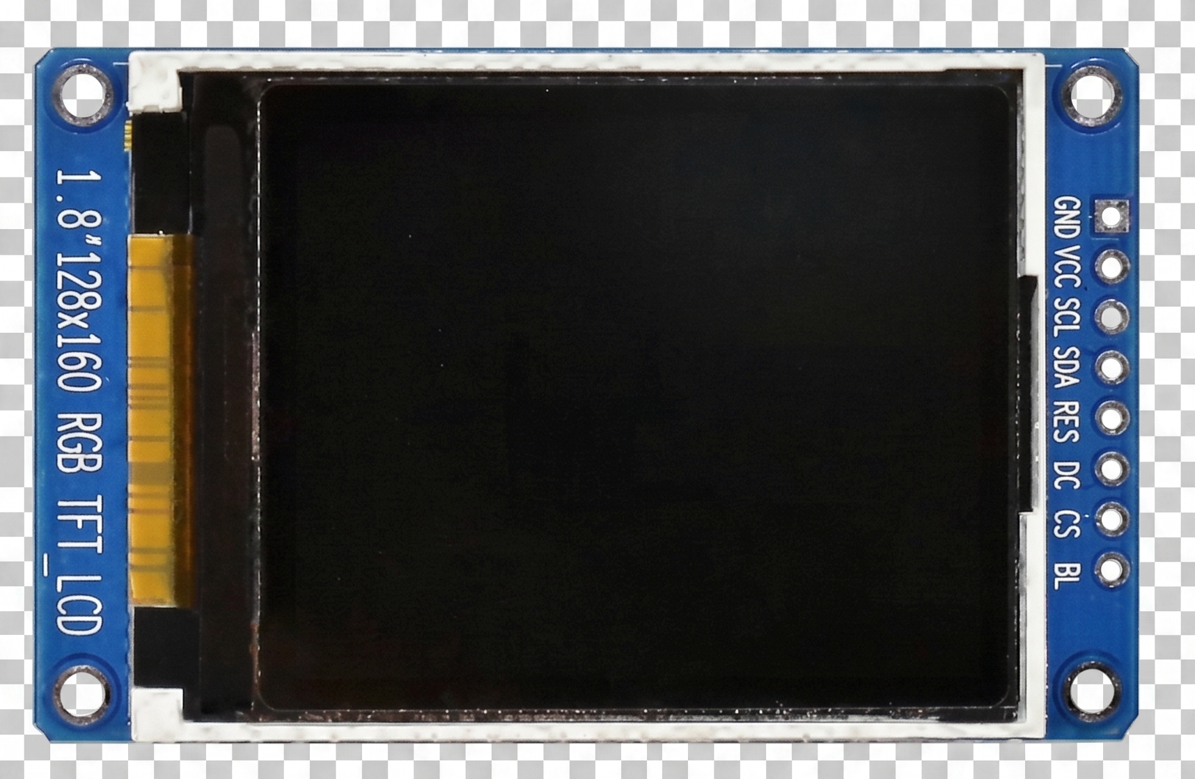
place images/ST7735R FRONT.png
Face · SPI
1.8″ ST7735S TFT
128×160 RGB display over SPI. Shows status and what A.I.L.Y.N heard. Pin names vary — match by function.
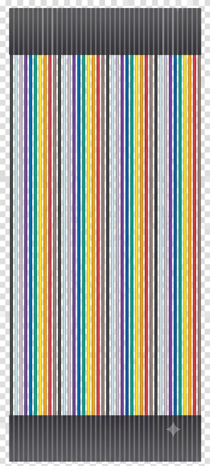
place images/fem-fem-dupont.png
Glue
DuPont jumpers
Female-to-female leads. The wiring guide colour-codes every connection so you can grab the matching lead.
03 / Wiring guide
Every connection, three ways
Same wiring shown as a colour legend, one master table, and a card per board. Colours match common DuPont lead colours — grab the colour the wire shows.
3V3 power
5V power
GND
Bit clock (BCLK/SCL)
Word select (WS/LRC)
Audio data
SPI data (SDA)
Chip select
Data/command
Reset
Before you plug anything in
The ICS-43434 mic is 3.3 V — a bare clone board can be damaged by 5 V (Adafruit's has a regulator and tolerates 3–5 V; if unsure, use 3V3). Power the mic and display from 3V3; only the amp's VIN goes to 5V for louder output.
Master pin map
Wire
Board pin
ESP32-S3
Signal
ICS-43434 microphone — I2S port 0 (input)
3V
→
3V3
Power (3.3 V only)
GND
→
GND
Ground
SEL
→
GND
Selects the left channel
BCLK
→
GPIO 4
Bit clock
LRCL
→
GPIO 15
Word select
DOUT
→
GPIO 16
Audio data out
MAX98357A amplifier — I2S port 1 (output)
VIN
→
5V
2.5–5.5 V; 5 V = loudest
GND
→
GND
Ground
BCLK
→
GPIO 5
Bit clock
LRC
→
GPIO 6
Word select
DIN
→
GPIO 7
Audio data in
SD
→
3V3
Keeps the amp enabled
—
GAIN
×
—
Leave open for 9 dB default
+ / −
→
Speaker
To the 40 mm speaker terminals
ST7735S display — SPI
GND
→
GND
Ground
VCC
→
3V3
Power
SCL
→
GPIO 12
SPI clock
SDA
→
GPIO 11
SPI data (MOSI)
RES
→
GPIO 8
Reset
DC
→
GPIO 9
Data / command
CS
→
GPIO 10
Chip select
BL
→
3V3
Backlight on
Board-by-board
images/ics-43434.jpg
MIC · ICS-43434
Microphone → I2S port 0
6 leads · logic 3.3 V
3Vpower3V3
GNDgndGND
SELleft chGND
BCLKclockGPIO 4
LRCLw-selGPIO 15
DOUTdataGPIO 16
images/MAX98357A_Amplifier.png
AMP · MAX98357A
Amplifier → I2S port 1
6 leads + speaker · VIN at 5 V
VIN5v5V
GNDgndGND
BCLKclockGPIO 5
LRCw-selGPIO 6
DINdataGPIO 7
SDenable3V3
+ / −speaker40 mm
images/ST7735R FRONT.png
TFT · ST7735S
Display → SPI
8 leads · logic 3.3 V
GNDgndGND
VCCpower3V3
SCLclockGPIO 12
SDAmosiGPIO 11
RESresetGPIO 8
DCd/cGPIO 9
CSc-selGPIO 10
BLlight3V3
Optional — your KY-037
The sound sensor can't capture speech, but it makes a fine "loud-sound" trigger while you're testing: + → 3V3, GND → GND, DO → GPIO 17 (leave AO unconnected). Turn the pot until DO flips on a clap.
04 / Setup & drivers
Get the toolchain ready
One-time setup in the Arduino IDE, then the display library needs a small config edit before it will light up.
Install the Arduino IDE 2.x, then open Settings and add this to Additional boards manager URLs: https://espressif.github.io/arduino-esp32/package_esp32_index.json
In Boards Manager, install esp32 by Espressif Systems. For the copy-paste audio sketches below, pick version 2.0.17 — see the version note.
Select the board ESP32S3 Dev Module. Under Tools, set USB CDC On Boot → Enabled and PSRAM → OPI PSRAM (if your module has PSRAM; otherwise Disabled).
In Library Manager, install TFT_eSPI by Bodmer. The audio sketches use the built-in I2S driver — no extra library needed.
Configure TFT_eSPI: open Documents/Arduino/libraries/TFT_eSPI/User_Setup.h and set the driver + pins to match the block below (comment out any conflicting lines already in the file).
Version note — read this
The audio sketches use the classic driver/i2s.h API, which is rock-solid on esp32 core 2.0.x. Core 3.x changed the I2S API — if you're on it, either select 2.0.17 in Boards Manager, or port the audio code to ESP_I2S.h / the arduino-audio-tools library. The display sketch works on either core.
Prove each piece works on its own before combining them. Flash stage 1, confirm it, move on. Debugging a whole assistant at once is where projects die.
Stage 1 · Display
ailyn_01_display.inoTFT_eSPI
/*  A.I.L.Y.N — Stage 1: Display test
    You should see the name and "DISPLAY OK" in green.
    Colours wrong or shifted? Change the tab colour in User_Setup.h.  */
#include <TFT_eSPI.h>

TFT_eSPI tft = TFT_eSPI();

void setup() {
  tft.init();
  tft.setRotation(1);                 // landscape 160x128
  tft.fillScreen(TFT_BLACK);

  tft.setTextColor(TFT_GREEN, TFT_BLACK);
  tft.setTextSize(2);
  tft.setCursor(8, 16);
  tft.println("A.I.L.Y.N");

  tft.setTextSize(1);
  tft.setTextColor(TFT_CYAN, TFT_BLACK);
  tft.setCursor(8, 48);
  tft.println("DISPLAY OK");

  tft.drawRect(4, 4, tft.width() - 8, tft.height() - 8, TFT_ORANGE);
}

void loop() {}
Stage 2 · Microphone
ailyn_02_mic.inocore 2.0.x
/*  A.I.L.Y.N — Stage 2: Microphone test (ICS-43434)
    Open Serial Monitor at 115200. The bar should jump when you speak.  */
#include <driver/i2s.h>

#define MIC_SCK   4     // BCLK
#define MIC_WS    15    // LRCL
#define MIC_SD    16    // DOUT
#define MIC_PORT  I2S_NUM_0

void micBegin() {
  i2s_config_t cfg = {
    .mode = (i2s_mode_t)(I2S_MODE_MASTER | I2S_MODE_RX),
    .sample_rate = 16000,
    .bits_per_sample = I2S_BITS_PER_SAMPLE_32BIT,
    .channel_format = I2S_CHANNEL_FMT_ONLY_LEFT,   // SEL wired to GND
    .communication_format = I2S_COMM_FORMAT_STAND_I2S,
    .intr_alloc_flags = ESP_INTR_FLAG_LEVEL1,
    .dma_buf_count = 4,
    .dma_buf_len = 256,
    .use_apll = false
  };
  i2s_pin_config_t pins = {
    .bck_io_num = MIC_SCK, .ws_io_num = MIC_WS,
    .data_out_num = I2S_PIN_NO_CHANGE, .data_in_num = MIC_SD
  };
  i2s_driver_install(MIC_PORT, &cfg, 0, NULL);
  i2s_set_pin(MIC_PORT, &pins);
}

void setup() {
  Serial.begin(115200);
  delay(400);
  micBegin();
  Serial.println("Mic ready - make some noise.");
}

void loop() {
  const int N = 256;
  int32_t buf[N];
  size_t bytesRead = 0;
  i2s_read(MIC_PORT, buf, sizeof(buf), &bytesRead, portMAX_DELAY);
  int samples = bytesRead / sizeof(int32_t);

  long peak = 0;
  for (int i = 0; i < samples; i++) {
    int32_t s = buf[i] >> 14;          // 24-bit sample, left-justified
    peak = max(peak, (long)abs(s));
  }
  int bars = map(min(peak, 30000L), 0, 30000, 0, 40);
  Serial.print('[');
  for (int i = 0; i < 40; i++) Serial.print(i < bars ? '#' : ' ');
  Serial.print("] ");
  Serial.println(peak);
  delay(50);
}
Stage 3 · Speaker
ailyn_03_speaker.inocore 2.0.x
/*  A.I.L.Y.N — Stage 3: Speaker test (MAX98357A)
    You should hear a short 440 Hz beep about once a second.  */
#include <driver/i2s.h>
#include <math.h>

#define AMP_BCLK  5
#define AMP_LRC   6
#define AMP_DIN   7
#define AMP_PORT  I2S_NUM_1
#define SR        16000

void ampBegin() {
  i2s_config_t cfg = {
    .mode = (i2s_mode_t)(I2S_MODE_MASTER | I2S_MODE_TX),
    .sample_rate = SR,
    .bits_per_sample = I2S_BITS_PER_SAMPLE_16BIT,
    .channel_format = I2S_CHANNEL_FMT_ONLY_LEFT,
    .communication_format = I2S_COMM_FORMAT_STAND_I2S,
    .intr_alloc_flags = ESP_INTR_FLAG_LEVEL1,
    .dma_buf_count = 8,
    .dma_buf_len = 256,
    .use_apll = false,
    .tx_desc_auto_clear = true
  };
  i2s_pin_config_t pins = {
    .bck_io_num = AMP_BCLK, .ws_io_num = AMP_LRC,
    .data_out_num = AMP_DIN, .data_in_num = I2S_PIN_NO_CHANGE
  };
  i2s_driver_install(AMP_PORT, &cfg, 0, NULL);
  i2s_set_pin(AMP_PORT, &pins);
}

void playTone(float freq, int ms) {
  int n = SR * ms / 1000;
  for (int i = 0; i < n; i++) {
    int16_t s = (int16_t)(3000 * sinf(2 * PI * freq * i / SR));
    size_t w;
    i2s_write(AMP_PORT, &s, sizeof(s), &w, portMAX_DELAY);
  }
}

void setup() {
  Serial.begin(115200);
  ampBegin();
}

void loop() {
  playTone(440, 200);
  i2s_zero_dma_buffer(AMP_PORT);
  delay(800);
}
Stage 4 · The assistant loop
This is the roadmap, not a finished sketch — it's the biggest stage and needs your Wi-Fi and a cloud API key. The scaffold shows the shape; you fill in record(), ask(), and speak() against your chosen provider.
ailyn_04_assistant.inoscaffold
/*  A.I.L.Y.N — Stage 4: assistant loop (scaffold)
    Combine stages 1-3, then fill in the cloud calls.  */
#include <WiFi.h>
#include <WiFiClientSecure.h>
#include <HTTPClient.h>

const char* WIFI_SSID = "your-network";
const char* WIFI_PASS = "your-password";
const char* API_KEY   = "your-api-key";   // keep secret - don't commit to GitHub

void setup() {
  Serial.begin(115200);
  // micBegin(); ampBegin(); tft.init();   // from stages 1-3
  WiFi.begin(WIFI_SSID, WIFI_PASS);
  while (WiFi.status() != WL_CONNECTED) { delay(300); Serial.print('.'); }
  Serial.println("\nOnline.");
}

void loop() {
  // 1. idle: wait for the wake word (ESP-SR WakeNet) or a KY-037 / button trigger
  // 2. record ~3-5 s from the mic  =>  WAV buffer in PSRAM
  // 3. POST audio to speech-to-text =>  text
  // 4. POST text to the LLM         =>  reply   (show it on the display)
  // 5. POST reply to text-to-speech =>  PCM/WAV  (ask for PCM to skip decoding)
  // 6. stream that audio to the MAX98357A
  // 7. back to idle
}
Next step for Stage 4
Start simple: skip the wake word at first and use the KY-037 or the BOOT button as your trigger, get one full cloud round trip working end-to-end, then layer WakeNet on top once the pipeline is proven.
06 / When it fights back
Common fixes
Screen is white, blank, or the colours are inverted
Almost always the tab colour. In User_Setup.h swap ST7735_GREENTAB for REDTAB, BLACKTAB, or GREENTAB2/3 and re-flash. If fully blank, recheck RES, DC, and CS.
Mic prints nothing or a flat number
Check SEL → GND, that power is 3V3 not 5V, and that BCLK/LRCL/DOUT aren't swapped. If it's silent, try I2S_CHANNEL_FMT_ONLY_RIGHT.
No sound from the speaker
Confirm SD → 3V3 (the amp is off otherwise), VIN → 5V, the speaker is on the + / − terminals, and DIN isn't mixed up with the clock pins.
Audio is quiet or distorted
Leave GAIN unconnected for the 9 dB default and power VIN from 5 V. Lower the amplitude in code if it's clipping.
i2s.h won't compile
You're on esp32 core 3.x. Select 2.0.17 in Boards Manager, or port to ESP_I2S.h / arduino-audio-tools.
Board won't upload or isn't detected
Hold BOOT, tap RST, release BOOT, then upload. Enable USB CDC On Boot, and make sure you're on the correct USB-C port — this board has two.